Machined parts ship within 7-15 days. Order your metal machined parts today!
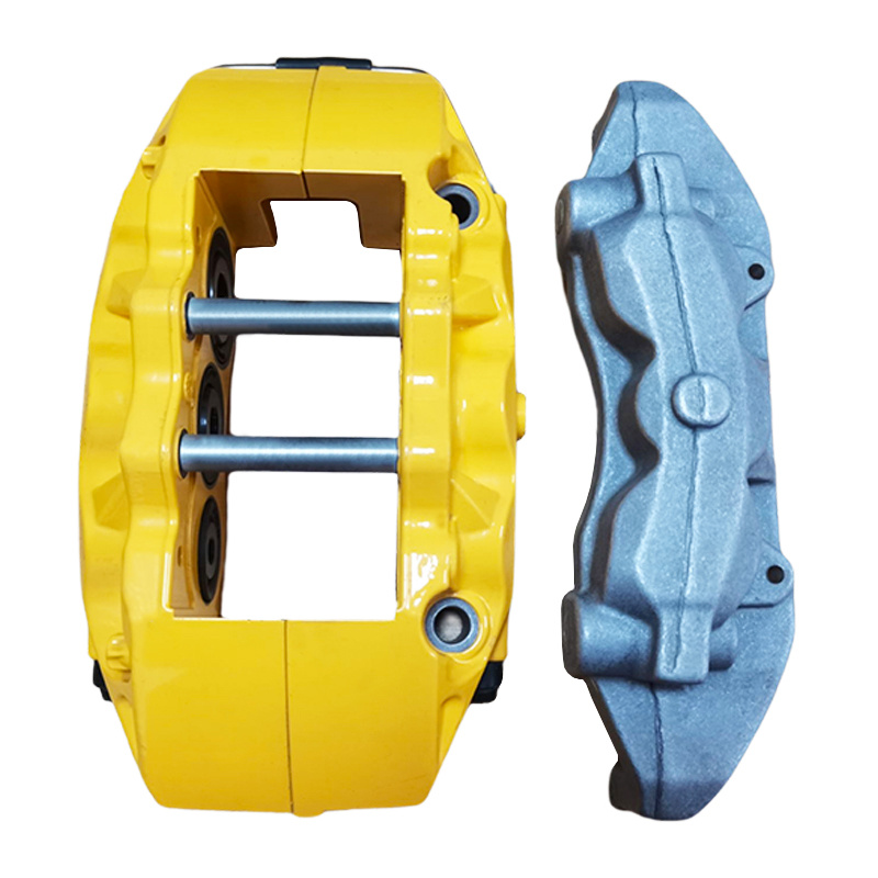
Yellow Anodized Aluminum Automotive Brake Caliper Forging Parts
|
Project |
Parameter |
|
Processing Type |
Precision forging+CNC machining |
|
Design Support |
2D/3D Drawing review,Prototype Development,OEM,ODM |
|
Material Capability |
Aluminum alloy, copper, steel, copper alloy |
|
Machining Accuracy |
±0.02mm |
|
Forging Accuracy |
±10mm |
|
Common Materials |
2014, 6061, 6063, 6082,7075, 7050, C1100, C1020 etc |
|
Quality Control |
Incoming Material, In-process, final inspection,IATF 16949 Certified,ISO 9001 Certified |
|
Surface Treatment |
Anodizing, sandblasting, polishing, electroplating, powder coating, blackening |
|
Manufacturing Process |
forging,T4 / T6 Heat Treatment,CNC machining, drilling, tapping, deburring, surface treatment,Packaging |
|
Processing Equipment |
forging equipment , Turn-Mill Machines, CNC lathes |
|
Testing Equipment |
Three coordinate inspection, NDT,hardness inspection, size inspection, Tensile Strength Testing, appearance inspection |
|
Service Content |
forging machining,Precision CNC Machining, surface treatment,OEM,ODM |
- Product Description
- Attributes
-
Yellow brake caliper components for passenger vehicles are safety-critical parts that convert hydraulic pressure into controlled clamping force at the wheel-end friction pair. The term “components” in this document refers to the caliper body or housing, bridge or carrier structure, piston, seals, dust boots, guide pins, pin bushings, anti-rattle hardware, pad retention features, mounting bosses, and associated fasteners. Because the assembly operates in a harsh thermal, mechanical, chemical, and vibrational environment, its engineering definition must address structural stiffness, corrosion resistance, fluid compatibility, fade performance, serviceability, and repeatable dimensional stability across the full manufacturing chain.
Simplified caliper architecture and load-transfer regions.
Typical manufacturing process chain for a caliper component family
Piston bore, seal, and dust-boot cross-section
Dimensional-control priorities in final inspection and process capability review 1. Functional Architecture and Component Breakdown
A modern brake caliper is a compact pressure vessel and structural clamp combined into one assembly. Its primary functional path begins at the hydraulic port, continues through the bore seal and piston, and terminates at the inner brake pad. Reaction force then travels through the bridge or carrier structure to the outer pad and finally into the knuckle or suspension upright through the mounting points. Each component must therefore satisfy a different but interdependent set of requirements.
The caliper body is the main structural housing and contains the hydraulic bore(s), pad window, and mounting interfaces. It is the most critical part from a stress and thermal perspective. The carrier or bracket, if the caliper architecture uses a floating arrangement, must preserve pad alignment and resist deformation under repeated clamping loads. The piston converts fluid pressure into mechanical displacement; it must have a controlled surface finish, stable geometry, and high corrosion resistance to avoid seal damage. Square-cut seals provide pressure recovery and retract the piston slightly when pressure is released, while dust boots keep debris and water away from the sealing surfaces. Guide pins and bushings permit self-alignment in sliding calipers and require low-friction surface treatment plus durable grease retention. Pad-retention hardware, anti-rattle springs, and fasteners are small in mass but high in system importance, because they determine rattle behavior, wear clearance, and serviceability.
For a yellow-coated product family, the caliper body and bracket are usually the visible elements and define the exterior aesthetic. A deep, even yellow color with controlled gloss level can differentiate the product without compromising thermal function. However, the coating system must be selected so that emissivity, thermal expansion, and edge coverage do not create localized hot spots or premature flaking. The product architecture should also consider accessibility for bleed screws, hose fittings, pad replacement, and piston retraction tools, because service operations are frequent throughout the life cycle.Component
Primary function
Critical characteristics
Typical material/process
Caliper body
Converts hydraulic pressure into pad clamp force
Bore concentricity, stiffness, corrosion protection
Forged/cast aluminum or cast iron; CNC machining; coating
Carrier/bracket
Transfers reaction loads to knuckle
Fatigue strength, bolt-hole accuracy, flatness
Forging or casting; machining; e-coat/powder
Piston
Applies hydraulic displacement to inner pad
Roundness, surface finish, fluid compatibility
Stamped steel, phenolic, or aluminum; turning/grinding; plating
Seals and dust boots
Fluid retention and contamination exclusion
Elastomer compatibility, compression set
EPDM molding; post-cure; assembly grease
Guide pins and bushings
Enable floating alignment
Low friction, wear resistance, straightness
Hardened steel; plating; precision ground
Retention hardware
Control pad and spring behavior
Spring force, fatigue life
Stainless or spring steel stamping/forming
Representative component breakdown and material/process mapping are shown in Table 1.
2. Material Selection and Surface Engineering
Material selection for brake caliper components is governed by a balance of stiffness, mass, thermal conductivity, corrosion performance, and manufacturability. For high-performance light-weight applications, aluminum alloys are common for the caliper body and carrier because they reduce unsprung mass and dissipate heat efficiently. Typical candidates include A356-T6 for cast structures, 6082-T6 or 6061-T6 for machined-from-billet or forged designs, and specialty forged aluminum alloys for premium performance programs. Cast iron remains attractive for certain heavy-duty or cost-sensitive products because of its excellent damping, wear behavior, and high-temperature stability, though it carries a mass penalty.
Piston material is chosen based on compatibility with fluid, temperature, and sealing strategy. Anodized aluminum pistons offer low mass and good corrosion resistance but require controlled hardness and surface finish. Phenolic pistons reduce heat transfer to the fluid, which can help prevent boil in extended high-thermal-load use; they are often selected for passenger-car calipers where pedal consistency is valued and piston temperature must be moderated. Steel pistons, usually plated, are robust and economical but transfer heat more readily and require strict corrosion control. Guide pins are commonly medium-carbon or alloy steel with zinc-nickel, Dacromet-type, or black oxide systems, depending on environmental exposure and OEM requirements.
The yellow finish itself is typically a multilayer surface system. For aluminum, a conversion coating or anodic base layer can be followed by powder coating or wet paint. Powder coating is preferred when edge coverage, chip resistance, and manufacturing throughput are important; it can deliver a uniform gloss and strong appearance in a single cycle. For steel carrier structures, phosphate or e-coat underlayers are commonly used to improve corrosion resistance, followed by the yellow topcoat. The coating thickness must be tightly controlled. Excessive film build may interfere with pad abutment, fastener fit, bleed screw access, or gasket seating; insufficient film thickness may reduce corrosion life and create visual inconsistency.
Because brake fluid and cleaning solvents can attack some organic coatings, chemical resistance testing is mandatory. Any chosen coating must withstand short-term exposure to DOT brake fluid, synthetic brake cleaner, salt fog, stone impact, and thermal cycling without blistering, softening, or delamination. The engineering team should define finish acceptance criteria for color tolerance, gloss range, adhesion rating, and distinctness of image if the product is positioned in the premium aftermarket segment.3. Manufacturing Processes and Process Chain
The manufacturing route depends on target cost, volume, weight, and performance. For a premium yellow caliper component set, the process chain is usually built around a near-net-shape structural blank followed by precision finishing operations. A forged aluminum caliper body begins with billet or preform heating, die forging, trimming, solution heat treatment, quenching, and artificial aging. Forging aligns the grain flow and improves fatigue strength relative to a fully machined billet part. In contrast, a cast aluminum body begins with low-pressure casting, gravity casting, or high-pressure die casting, followed by heat treatment to stabilize properties and reduce porosity effects. Cast iron calipers may be produced by sand casting or controlled permanent-mold routes where damping and cost are prioritized.
After primary forming, CNC machining establishes all critical interfaces: piston bores, mounting ears, hose ports, pad abutment surfaces, bleed screw threads, guide pin bores, and datum faces. Multi-axis machining centers are favored because they reduce setups and improve positional accuracy. Finish boring and reaming may be used to achieve bore geometry within tight cylindricity requirements. Threaded features are typically produced by tapping or thread milling followed by gauging. If the body contains internal fluid galleries, drilling and cross-drilling operations must be controlled for burr height, and all passages must be deburred and cleaned to prevent hydraulic contamination.
Surface preparation is an often underestimated but decisive phase. Prior to coating, parts are chemically cleaned, rinsed, and dried; some programs include shot blasting or controlled micro-abrasive texturing to stabilize adhesion. For aluminum, conversion coating or anodizing provides a chemically active and corrosion-resistant base. For steel parts, phosphate or e-coat may be used as primer systems. Yellow powder or paint application then follows, with cure schedules tuned to avoid dimensional drift or distortion. Because the part functions near brake heat sources, post-cure verification is essential: the film must retain appearance and adhesion after repeated thermal cycles.
Assembly operations integrate elastomer seals, pistons, bleeds, and guide hardware under clean conditions. Lubricants are applied in metered amounts to the piston seal and guide pin interfaces, and each subassembly is checked for smooth movement, seal seating, and absence of particulate contamination. Final build quality depends heavily on cleanliness discipline, because small foreign particles can cause seal scoring, fluid bypass, or stick-slip motion. The process chain should therefore be defined as a controlled production system with in-process checks at every major transformation stage rather than a simple sequence of operations.Operation
Typical objective
Key control variable
Common defect
Mitigation
Forging/casting
Create near-net structural blank
Porosity, grain flow, shrinkage
Internal voids, warpage
Process window validation, NDT, die control
CNC machining
Generate functional datums and bores
Tool wear, positional tolerance
Out-of-round bores, misalignment
Tool life management, probing, SPC
Deburr/clean
Remove burrs and contamination
Residual chips, sharp edges
Seal damage, fluid contamination
Wash systems, visual + borescope inspection
Coating
Provide yellow aesthetic and corrosion protection
Film thickness, cure temperature
Orange peel, blistering, thin edges
Pre-treatment control, oven mapping
Assembly
Install seals, pistons, pins
Lubricant amount, cleanliness
Stiction, leak risk
Controlled work instructions, contamination control
Test
Verify performance and leak integrity
Pressure, displacement, torque
Leakage, drag, rattle
100% leak test, functional fixtures
Table 2 summarizes the dominant process controls and common failure modes across the build chain.
4. Dimensional Control, GD&T, and Tolerance Strategy
Dimensional control is central to brake caliper performance because the assembly must seal hydraulic pressure, move without binding, and maintain pad alignment under load. A functional GD&T scheme should be built from a clear datum hierarchy. Typically, the primary datum is a machined mounting face or bracket interface that defines the installation plane. The secondary datum may be the bore axis or a pair of locating holes that establish the caliper orientation. The tertiary datum often references a pad abutment face, thread feature, or auxiliary indexing surface. Once the datum frame is established, bore position, coaxiality, flatness, and parallelism can be controlled relative to functional requirements rather than arbitrary geometry.
Representative tolerance values depend on architecture, but the bore diameter and surface finish are usually among the most critical dimensions. Hydraulic bores may require tight roundness, cylindricity, and low roughness to support seal durability and smooth piston motion. Guide-pin holes must be straight, parallel, and positioned symmetrically so that floating calipers can retract evenly. Pad-window dimensions must allow installation of friction material with controlled clearance; too little clearance may cause drag or noise, while too much clearance encourages rattle and uneven wear. Fastener hole location and bracket flatness are essential to avoiding assembly-induced preload and rotor drag.
CMM inspection is recommended for structural critical characteristics, especially after machining and finishing. Bore gauges, air gauges, thread gauges, coating thickness instruments, and torque auditing tools support shop-floor verification. Process capability indices should be tracked for all special characteristics. A stable process may still be unacceptable if it cannot maintain Cp and Cpk targets across shifts, tool changes, and surface treatments. For braking components, variation is often more important than nominal value because stack-up directly affects pedal feel, pad drag, and service life.
The yellow coating can complicate tolerance control because film thickness adds material to every exposed surface. The engineering team should therefore define machined masking zones or post-coating machine-up features where necessary. Pads, slide interfaces, sealing lands, and bolt faces should remain free of excessive coating build. Edges must be verified for coverage and absence of pinholes; however, too much build in thread roots or bores can make assembly difficult and create false nonconformances during gauging. This is why coating design must be integrated with CAD datums and manufacturing planning from the earliest phase rather than treated as a cosmetic afterthought.
Simplified piston bore and seal stack cross-section 5. Validation, Inspection, and End-of-Line Testing
Validation for brake caliper components must reflect the safety-critical nature of the product and the real-world severity of service. Mechanical validation usually includes static pressure tests, burst tests, stiffness evaluation, piston retraction assessment, pad drag force measurements, and fatigue cycling under thermal load. A floating caliper should be tested for lateral compliance, while a fixed caliper may require multi-piston synchronization checks. High-temperature fade simulations and stop-energy duty cycles are often used to verify that the coating, seals, and lubricants do not degrade in a way that alters feel or leakage behavior.
Leak testing is a core production requirement. A component that appears cosmetically acceptable may still contain microcracks, incomplete sealing, or machining defects that only become visible under hydraulic pressure. Pressure decay, air-under-water bubble tests, or automated helium-based systems can be selected depending on the cost target and leakage sensitivity. For premium products, 100% end-of-line leak testing is recommended. Functional drag checks on guide hardware and piston movement provide a second layer of assurance, because a caliper can be leak-tight yet still exhibit unacceptable stiction.
Corrosion testing should include salt spray or cyclic corrosion exposure, especially for the yellow external finish and plated hardware. The purpose is not simply to observe rust but to understand how coating breakdown progresses at edges, fastener heads, and masked interfaces. Adhesion testing, such as cross-hatch or pull-off evaluation, should be performed on representative witness coupons from each batch or load. Color and gloss checks are important for brand consistency, but they also serve as indirect indicators of film thickness and cure uniformity. In a production environment, statistical process control charts should monitor critical dimensions, coating thickness, and test pass rates so that drift can be corrected before scrap or field failures occur.
Inspection equipment must be calibrated and traceable. Gages used for bore diameter, runout, and thread quality should be audited on a defined interval. Visual inspection criteria should be documented with boundary samples to reduce inspector variation. Because bright yellow surfaces can reflect light strongly, lighting geometry and operator training become more important than they are for dark or matte finishes.
Dimensional-control priorities in final inspection and process capability review 6. Assembly Practices, Service Considerations, and Failure Analysis
Assembly quality directly influences both warranty performance and perceived product quality. Seal installation should use clean gloves, approved assembly grease, and tools that prevent nicking or twisting of the elastomers. The piston must be inserted with controlled axial force to avoid seal roll or dust-boot damage. Guide pins should be lubricated with a grease specified for the temperature and elastomer system, and any excess lubricant should be removed to avoid contamination migration. Fasteners must be torqued using calibrated tools and, where specified, threadlocking compounds or prevailing-torque hardware. Reusable fasteners should have a defined inspection and replacement criterion, particularly when they are exposed to corrosion or repeated thermal cycling.
Maintenance requirements should be considered already during design. A caliper assembly that is difficult to bleed, seal, or service will create field support issues even if it passes initial validation. Bleed screw access, hose orientation, pad replacement path, and piston retraction tooling should all be included in the design review. For a yellow-coated product, service scratching is a concern; therefore, chamfers and tool-access design should minimize accidental cosmetic damage during maintenance.
Common failure modes include leakage from seal wear, uneven pad wear due to guide pin stiction, coating discoloration from excessive heat, corrosion at masked interfaces, and brake drag caused by piston contamination or bore scoring. Root-cause analysis should distinguish between design-related failures, manufacturing escape defects, and service-induced damage. For example, drag caused by contaminated guide pins may indicate inadequate cleaning or lubrication control, while leakage from the piston seal may indicate bore roughness, piston surface damage, or seal material incompatibility. The value of a structured failure-analysis loop is that it feeds back into material selection, process windows, and test criteria rather than simply confirming a part has failed.
The yellow surface finish can also serve as a diagnostic aid. Changes in gloss, blistering, or color shift may visually warn of heat exposure or chemical attack before structural issues become obvious. However, the finish should never be relied upon as the only indicator of product health. Engineering controls, not appearance, are the basis of acceptable quality.7. Environmental, Regulatory, and Program Management Considerations
Automotive brake components are subject to a broad set of environmental and program-management expectations. Material declarations, restricted substance compliance, and end-of-life recyclability increasingly influence supplier selection. Aluminum components are attractive because they can be recycled efficiently, while plated or coated steel hardware should be specified with awareness of chromium-free or low-emission process options when possible. Paint and coating systems should be selected to reduce volatile organic compound emissions and to support repeatable production at scale.
Program management should define the product at multiple maturity gates: concept design, prototype build, process qualification, pilot production, and volume release. Each gate should include documented deliverables such as CAD models, DFMEA, PFMEA, control plan, process flow, test reports, and approved visual standards. Because brake caliper components are safety-related, change control must be strict. Any modification to material grade, heat treatment cycle, coating supplier, seal compound, or machining program should trigger re-validation. Even a seemingly minor alteration can change friction behavior, seal life, or cosmetic appearance.
Packaging and logistics are also part of quality. Yellow coated surfaces are vulnerable to scuffing, and precision bores can be damaged by chips or handling debris. Protective caps, partitioned packaging, and corrosion-inhibiting materials should be used to preserve condition through storage and transport. Traceability labels should link parts back to lot numbers, heat codes, and inspection results so that field issues can be isolated quickly. From a customer perspective, product quality is often experienced not only through performance but through arrival condition, completeness, and consistency across batches.
Overall, the highest-performing programs treat the brake caliper not as a simple hardware item but as an integrated engineered system. When materials, manufacturing, finishing, inspection, and validation are managed as one discipline, the result is a component set that can deliver repeatable braking performance, aesthetic durability, and strong manufacturing economics.8. Conclusion and Recommended Technical Position
A yellow car brake caliper component set should be engineered with the same rigor applied to any other safety-critical automotive subsystem. The engineering goal is not merely to create a visually distinctive product but to balance clamp force, stiffness, corrosion resistance, heat behavior, serviceability, and repeatable manufacturability. The strongest technical approach usually combines a structurally efficient caliper body, appropriately selected piston and seal materials, controlled coating technology, and a manufacturing flow built around precision machining and validated clean assembly.
From a manufacturing standpoint, the preferred path is one that minimizes secondary handling while maximizing dimensional stability. Forged or high-quality cast blanks, followed by controlled heat treatment and CNC finishing, provide a reliable foundation. Surface engineering must be integrated early, especially because the yellow finish is both a brand differentiator and a technical protection layer. Inspection should be anchored to functional characteristics rather than appearance alone. Final qualification should include pressure integrity, mechanical stiffness, coating durability, corrosion resistance, and repeatable assembly feel.
For organizations developing or sourcing such a product, the most important success factor is cross-functional discipline. Design, materials, manufacturing, quality, and field-service concerns must all be resolved together. That is how a brake caliper component program transitions from a concept with strong visual appeal into a robust industrial product suitable for demanding road use. -
Project
Parameter
Processing Type
Precision forging+CNC machining
Design Support
2D/3D Drawing review,Prototype Development,OEM,ODM Material Capability
Aluminum alloy, copper, steel, copper alloy
Machining Accuracy
±0.02mm
Forging Accuracy
±10mm
Common Materials
2014, 6061, 6063, 6082,7075, 7050, C1100, C1020 etc
Quality Control
Incoming Material, In-process, final inspection,IATF 16949 Certified,ISO 9001 Certified
Surface Treatment
Anodizing, sandblasting, polishing, electroplating, powder coating, blackening
Manufacturing Process
forging,T4 / T6 Heat Treatment,CNC machining, drilling, tapping, deburring, surface treatment,Packaging
Processing Equipment
forging equipment , Turn-Mill Machines, CNC lathes
Testing Equipment
Three coordinate inspection, NDT,hardness inspection, size inspection, Tensile Strength Testing, appearance inspection
Service Content
forging machining,Precision CNC Machining, surface treatment,OEM,ODM
Rapid lead times starting from just 1 business day.
ISO 9001,ISO 14001,IATF 16949 and AS9100D Certification.
Over 100 materials available, with 50+ surface finish options.
Cost-effective mass production.
Order as low as 1 piece.