Machined parts ship within 7-15 days. Order your metal machined parts today!
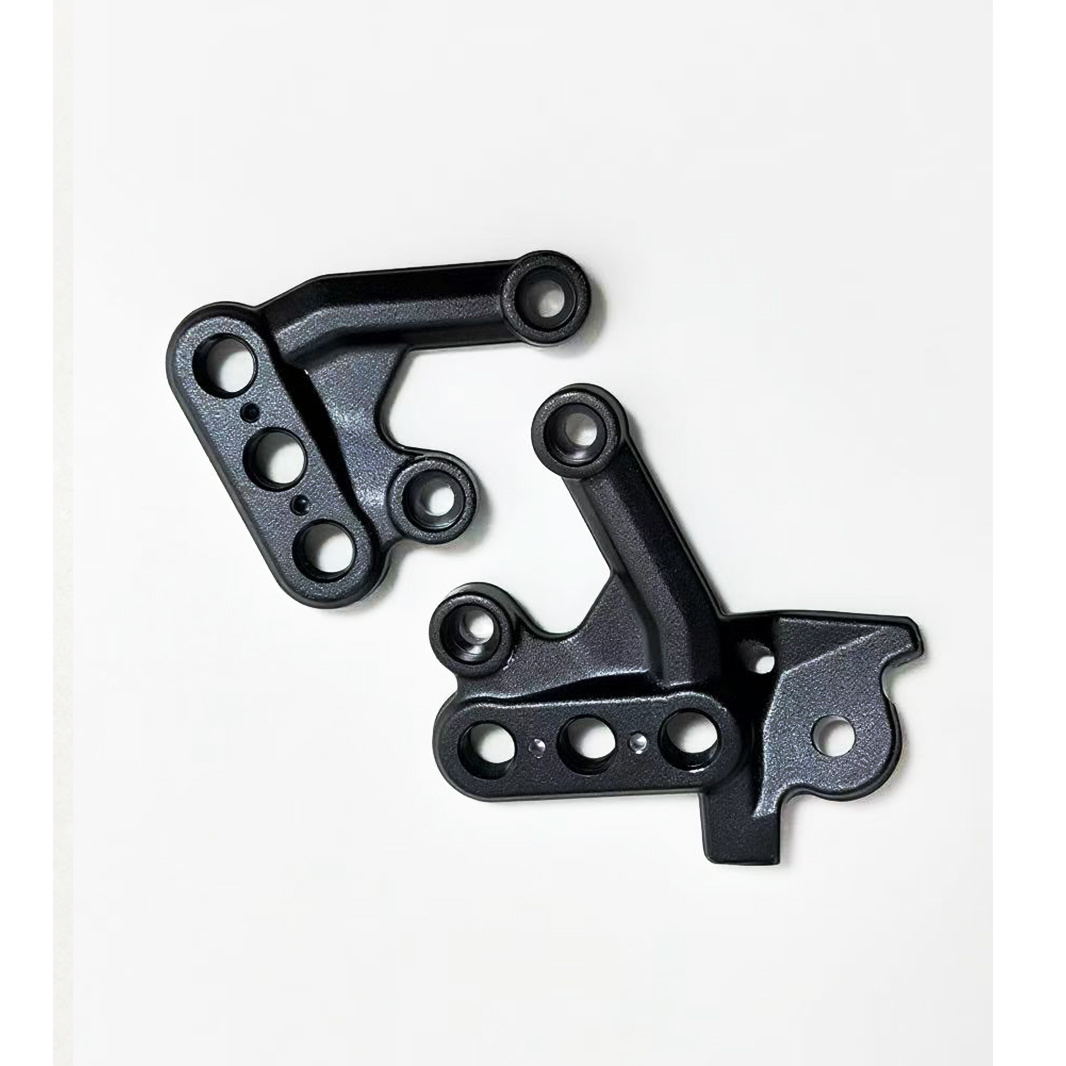
Custom Aluminum Forged Bicycle Left & Right Pedal Brackets | OEM Bicycle Parts
|
Project |
Parameter |
|
Processing Type |
Precision forging+CNC machining |
|
Design Support |
2D/3D Drawing review,Prototype Development,OEM,ODM |
|
Material Capability |
Aluminum alloy, copper, steel, copper alloy |
|
Machining Accuracy |
±0.02mm |
|
Forging Accuracy |
±10mm |
|
Common Materials |
2014, 6061, 6063, 6082,7075, 7050, C1100, C1020 etc |
|
Quality Control |
Incoming Material, In-process, final inspection,IATF 16949 Certified,ISO 9001 Certified |
|
Surface Treatment |
Anodizing, sandblasting, polishing, electroplating, powder coating, blackening |
|
Manufacturing Process |
forging,T4 / T6 Heat Treatment,CNC machining, drilling, tapping, deburring, surface treatment,Packaging |
|
Processing Equipment |
forging equipment , Turn-Mill Machines, CNC lathes |
|
Testing Equipment |
Three coordinate inspection, NDT,hardness inspection, size inspection, Tensile Strength Testing, appearance inspection |
|
Service Content |
forging machining,Precision CNC Machining, surface treatment,OEM,ODM |
- Product Description
- Attributes
-
1. Bicycle Pedals Summary
Bicycle left and right pedal components form a deceptively compact but highly engineered interface between the rider and the drivetrain. Their design governs not only power transfer efficiency, but also rider comfort, platform stability, safety under dynamic loading, and long-term reliability in wet, dusty, and impact-prone environments. In production bicycles, pedals are expected to tolerate cyclic leg forces, repeated ingress of contamination, torsional shock from clipping in or out, curb strikes, and wide temperature and humidity excursions without loss of function. The component set also carries a critical user-facing requirement: the left and right pedals must be unambiguously differentiated at the thread interface, because the left-side spindle typically uses a reverse, or left-hand, thread to prevent self-loosening during operation.
From a manufacturing standpoint, pedal components are a multi-process product family. Material choice influences every downstream decision, from forming route and heat treatment to machining allowances, wear protection, and final inspection. High-load systems often rely on forged aluminum bodies and heat-treated alloy steel or chromoly axles; lightweight systems may employ reinforced polymer bodies with stainless or hardened steel inserts. Bearing arrangements can include loose ball bearings, cartridge bearings, or polymer bushings, with seal architecture selected to suit maintenance interval and contamination tolerance targets. Quality assurance must therefore combine dimensional verification, thread gauge control, torque retention monitoring, fatigue testing, salt spray or corrosion exposure, and functional spin tests.
2. Component Overview and Functional Architecture
A bicycle pedal assembly is usually split into a left-hand and right-hand unit, each of which mounts to the corresponding crank arm. Although the visual architecture can appear symmetrical, the spindle thread direction, marking convention, and often the internal bearing stack are oriented to match the directional loads experienced during rotation. The right pedal generally employs a conventional right-hand thread; the left pedal uses a left-hand thread so that pedaling loads do not tend to unscrew the spindle during service. This detail is fundamental to field reliability and must be preserved throughout design, machining, and assembly.
The assembly may be considered in four mechanical domains. The first is the interface domain, consisting of the thread, spindle shoulder, wrench flats, and anti-rotation features. The second is the support domain, made up of bearings, sleeves, bushings, and preload elements that establish rotational smoothness and axial control. The third is the engagement domain, including the pedal body, cage geometry, traction pins, and contact texture that communicate force from shoe to platform. The fourth is the environmental domain, which includes seals, end caps, lubrication reservoirs, coatings, and drainage paths that preserve function in abusive service conditions. Effective pedal engineering balances these domains rather than optimizing only one of them.
Component differentiation by application is also important. Road pedals prioritize mass efficiency, aerodynamic packaging, and precise engagement when clipless systems are used. Mountain and trail pedals prioritize mud shedding, impact resistance, replaceable pins, and bearing survivability under frequent washdown. Urban and trekking pedals often emphasize safety reflectors, broad platform stability, and low maintenance. E-bike applications may create higher torque accumulation and longer duty cycles, which places added stress on the spindle and bearing system. A unified design therefore needs a well-defined load envelope and a clear specification of service class.
Exploded schematic of left/right pedal assembly Subcomponent
Primary function
Typical materials
Key control characteristics
Pedal body
Transfers rider load and defines footprint
Aluminum alloy, reinforced nylon, composite
Flatness, pin retention, surface finish, mass
Spindle / axle
Provides rotation axis and crank interface
Chromoly, alloy steel, stainless steel
Thread form, hardness, concentricity, fatigue strength
Bearings / bushings
Supports rotation and reduces friction
Steel bearings, cartridge units, polymer bushings
Radial clearance, preload, lubrication retention
Seals and caps
Exclude contaminants and retain grease
NBR, FKM, TPU, molded polymer
Compression set, fit, abrasion resistance
Traction elements
Improve shoe grip
Steel pins, molded texture, carbide tips
Projection height, thread engagement, wear rate
Fasteners
Maintain assembly integrity
Stainless steel, alloy steel
Torque retention, corrosion resistance, stripping margin
3. Design Requirements and Performance Targets
The design requirement set begins with static and dynamic load capacity. Pedals are repeatedly loaded by a human rider through cyclic compression and shear, with peak force concentrated during sprinting, climbing, and standing starts. In service, local force may be concentrated at the foot contact zone while the spindle experiences bending and torsion. The pedal body must not crack, deform permanently, or allow excessive pin pull-out. The spindle must survive bending fatigue with an appropriate safety factor, while bearings must maintain acceptable drag and radial play over the intended life cycle.
Ergonomics are a structural requirement, not merely a comfort feature. Platform size, concavity, pin arrangement, and corner radii influence foot retention and pressure distribution. A pedal body that is too small can increase hot spots and reduce stability; one that is too large can increase strike risk and mass. The ideal geometry is application-specific and should be validated against shoe size distributions, riding posture, and expected cadence ranges. In clipless pedals, retention and release forces must remain consistent across temperature and contamination states to avoid accidental disengagement or difficult egress in an emergency.
Thread integrity is one of the most failure-sensitive requirements. Left and right pedals must be laser-marked, stamped, or otherwise permanently identified with L and R, and the markings should remain legible after finishing and field use. Thread lead-in chamfers must support smooth installation without galling, and the thread class should be chosen to provide sufficient engagement length without excessive play. For metal spindles, thread rolling is often preferred where practicable because it can improve surface integrity and fatigue resistance relative to aggressive cutting methods.
Another core design target is bearing service life. Pedal bearings often operate with limited size, minimal radial envelope, and significant exposure to water and grit. The bearing stack should therefore be tolerant of contamination and simple to service or replace where the market segment supports maintenance. In premium designs, the spindle may include dual cartridge bearings separated by a spacer sleeve and protected by multiple seal stages. In cost-sensitive designs, a bushing at the outboard side and a bearing at the inboard side may provide a satisfactory compromise between cost and durability.
Surface protection is the final major requirement family. Pedals see direct stone impact and repeated abrasion from shoes and debris. Anodized aluminum, e-coated steel, phosphate pre-treatments, PTFE-infused coatings, or molded-in color systems can all be applied depending on the substrate. The coating system must not interfere with thread tolerances, bearing fits, or pin assembly, and it must survive the thermal and chemical profile of the production line. Because pedals are frequently washed or ridden through salt-laden environments, corrosion resistance has a direct effect on perceived product quality as well as actual durability.
4. Material Selection
Material selection should begin by defining the mechanical duty class. A forged aluminum platform pedal typically uses a 6xxx or 7xxx alloy for the body, balancing machinability, corrosion resistance, weight, and strength. Forged 6061-T6 is common for robust and economical bodies because it provides a favorable ratio of strength to manufacturability and is compatible with anodizing. Where higher strength is needed, more advanced alloys may be used, though they can impose tighter process controls and higher cost. Stainless steel is less common for entire bodies but can appear in pins, springs, or fasteners where corrosion performance is critical.
The spindle is often the most heavily loaded structural part and is usually made from alloy steel or chromoly. Typical requirements include high yield strength, fatigue resistance, machinability, and surface hardenability. Heat treatment is frequently necessary to achieve the final balance of core toughness and surface wear resistance. Where weight and corrosion resistance are prioritized, stainless steel can be considered, but the designer must account for differences in strength-to-weight ratio and potential effects on bearing wear. Threaded spindle geometry must preserve root integrity under torque and bending, especially around the shoulder transition region where stress concentration is highest.
Polymer pedal bodies typically use glass-fiber-reinforced nylon, reinforced polypropylene, or engineered thermoplastic composites. These materials can reduce mass, simplify molding of complex geometries, and provide low noise and low thermal conductivity. However, they require careful design around creep, moisture absorption, UV aging, and impact behavior at low temperature. Insert-molded steel threads or spindle carriers may be needed to secure long-term reliability. Composite materials such as carbon-fiber-reinforced polymers can offer performance benefits in premium products, but they demand tight control of fiber orientation, resin content, and impact damage tolerance.
Bushings, seals, and contact inserts require their own material logic. Bushings may use bronze, PTFE-filled polymer, or sintered materials depending on cost and lubrication strategy. Seals are commonly nitrile rubber or fluorocarbon elastomers; the choice depends on temperature range, lubricant compatibility, and exposure to cleaning chemicals. Traction pins are usually hardened steel with thread-locking features or knurled bodies to prevent loosening. If reflectors or safety markers are included, the optical and impact requirements of those elements must be balanced against the structural envelope of the pedal body.
A practical sourcing program should define a controlled bill of materials with allowable alternates. Each alternate material should be tied to a formal equivalency evaluation that includes mechanical properties, corrosion behavior, processing windows, and downstream impact on assembly. Where possible, the design should avoid using exotic materials in low-value functions, reserving premium substrates for the spindle and wear interfaces. The table below summarizes a common material allocation strategy for a high-volume platform pedal program.
Part
Preferred material
Why it is used
Main risk if substituted
Pedal body
6061-T6 forged aluminum or reinforced nylon
Strength-to-weight ratio, cost, finish compatibility
Warping, low fatigue margin, dimensional drift
Spindle
Chromoly steel with heat treatment
Bending fatigue resistance and thread durability
Thread wear, cracking, or excessive mass
Bearings
52100 steel or sealed cartridge units
Low friction and established supply base
Reduced life or contamination sensitivity
Pins
Hardened steel
Wear resistance and grip stability
Bending, stripping, or corrosion
Seals
NBR or FKM
Grease retention and contamination protection
Compression set and leakage
Fasteners
Stainless or coated alloy steel
Corrosion resistance and torque stability
Galling or rust
Simplified cross-section of pedal bearing stack 5. Manufacturing Processes
The manufacturing route for bicycle pedal components depends on the selected architecture, but the process chain generally includes near-net-shape forming, precision machining, surface treatment, component cleaning, assembly, and final verification. Forged aluminum pedal bodies usually begin with billet preparation and hot or warm forging to align grain structure with the load path. Forging offers superior fatigue resistance compared with simple machining from solid stock because material flow can be oriented around the pedal’s high-stress regions. After forging, secondary operations such as trim removal, CNC contouring, hole drilling, thread insertion, and pin-seat machining complete the geometry.
For pedal bodies produced by injection molding, the tool design must consider gate placement, weld line location, glass-fiber orientation, and post-mold shrinkage. Molded bodies can integrate complex grip patterns, reflectors, and internal ribs at relatively low unit cost, but the process requires careful attention to fiber distribution and long-term creep. If threaded inserts or steel spindle carriers are used, insert-molding must provide sufficient retention without inducing knit-line weakness. Process capability studies are recommended for critical dimensions such as bearing bores, axial alignment, and reflector pocket depth.
The spindle and axle route is typically more controlled and more inspection-intensive than the body route. Raw bar stock is cut, center-drilled where needed, turned on CNC lathes, thread-rolled or thread-cut, and then heat-treated according to material requirements. After heat treatment, critical surfaces may be ground to achieve precise bearing journals and seal interfaces. Thread formation deserves special attention. Rolling can improve fatigue strength by introducing compressive surface residual stress and preserving grain continuity, but it requires accurate preform diameter and suitable material ductility. Where thread cutting is used, tool wear and burr formation must be monitored to avoid galling during installation.
Surface finishing is selected according to substrate and market class. Aluminum bodies often receive anodizing, which provides corrosion resistance and a visually consistent appearance. Prior to anodizing, the surface may be blasted or polished to create the desired texture. Steel spindles may be black oxide treated, zinc plated, phosphate coated, or otherwise protected depending on corrosion requirements and bearing compatibility. Polymer bodies may be dyed in-mold or painted with special coatings, though many molded colors avoid secondary paint steps to reduce cost and environmental burden. Traction pins may be separate fasteners or molded features, with thread locker or mechanical retention applied as required.
Assembly is a precision operation rather than a simple joining step. Bearings are pressed or inserted into the body, spacers are placed to set preload, seals are seated without nicking, grease is applied at controlled quantity, and spindle retention is verified by torque measurement or rotation torque testing. If the pedal incorporates serviceable bearings, the assembly must also support disassembly without damaging the bore. Lubricant selection matters because grease rheology affects drag, sealing, and corrosion protection. A general-purpose lithium complex grease may be suitable for broad applications, whereas specialty low-temperature or high-washout greases may be preferable in demanding conditions.
The process flow below shows a representative high-volume route and highlights the point at which process capability and inspection gates are most important. A robust factory layout should combine in-process gauging with line-side error proofing to prevent left/right mix-ups, thread orientation errors, or missing fasteners. Traceability should capture raw material lot, spindle heat treatment batch, surface finish batch, and final assembly date.
Process flow for pedal component manufacturing 6. Detailed Process Control Strategy
Process control begins with incoming raw materials. Certificates of analysis should be reviewed for chemistry, mechanical properties, and heat-treatment condition where applicable. For forged bodies, billet dimensions and grain quality should be confirmed. For polymers, moisture content, melt flow behavior, and filler content should be monitored. Incoming inspection should also verify bearing suppliers, seal durometer, fastener coating thickness, and pin geometry. When supply chains are global, incoming qualification should be repeated after any supplier change, tool relocation, or chemistry revision.
During machining, the most important controls are datum consistency, tool wear management, and chip evacuation. Pedal bodies often have multiple bearing bores, threaded holes, and cosmetic surfaces that must remain aligned. A stable datum strategy prevents cumulative error between the spindle axis, pin grid, and side profile. Tool wear directly affects bore diameter and thread quality, so production should use statistical process control and scheduled tool replacement based on measured drift rather than purely on machine runtime. Burrs, especially around threaded interfaces and pin holes, must be removed because even small burrs can interfere with assembly and generate customer complaints.
Heat treatment is a special process that requires documented furnace calibration and load mapping. Spindles that are not properly heat treated may show inconsistent hardness, residual stresses, or distortion that complicates thread fit and bearing alignment. Post-treatment hardness testing should be linked to lot traceability and, where necessary, microstructure checks. For plated or coated parts, pre-treatment cleaning and activation are equally important. Poor surface preparation can lead to coating adhesion failures, blistering, or early corrosion, all of which are unacceptable for a part that is exposed to spray, road grime, and repeated handling.
Assembly-line control must include poka-yoke features to prevent reversed components and incorrect torque application. Left and right pedals should be color-coded, laser marked, or fixture-keyed so that operators cannot accidentally swap them. Torque tools should be periodically calibrated, and their digital logs should be preserved. The final assembly should include a rotation check, side-play measurement, and a visual seal inspection. In premium products, torque-to-rotate curves can be recorded to verify bearing preload consistency and to detect lubricant or seal anomalies.
A strong process strategy also plans for rework and repair. Because the spindle thread and bearing bores are critical interfaces, rework options are limited and should be formally defined. Minor cosmetic defects can sometimes be re-finished, but dimensional errors usually require rejection. The production line should therefore prioritize first-pass yield through fixture accuracy, operator training, and process audit. In practice, the lowest-cost pedal is not the one with the cheapest raw material, but the one with the most stable process route and the least defect escape risk.
7. Quality Control and Validation
Quality control for pedal components spans metrology, functional verification, and durability validation. Dimensional inspection should include overall pedal length, platform width, thickness, spindle runout, bearing seat diameter, pin projection, thread pitch diameter, and critical edge radii. Metrology tools may include coordinate measuring machines, optical comparators, thread gauges, surface roughness testers, and go/no-go fixtures. For high-volume production, a combination of full inspection for critical dimensions and statistical sampling for secondary dimensions is usually most practical.
Inspection item
Method
Typical acceptance intent
Thread orientation and marking
Visual + thread gauge
Left and right parts must be unmistakably differentiated
Bearing bore diameter
Plug gauge / CMM
Proper interference or clearance fit
Spindle runout
Dial indicator / CMM
Within controlled concentricity window
Surface roughness
Profilometer
No abrasive or sealing damage risk
Pin retention
Torque or pull-out test
No loosening under service vibration
Assembly drag
Torque-to-rotate test
Smooth rotation without excessive preload
Corrosion resistance
Salt spray or humidity exposure
No functional degradation beyond spec
Fatigue life
Cyclic loading rig
No fracture or unacceptable looseness
Functional testing should reproduce the actual loading pattern as closely as practical. A pedal fatigue test must address repeated axial force, eccentric loading, side impact, and exposure to contaminants. For a platform pedal, the test protocol can use a servo-hydraulic rig that applies cyclic vertical load while introducing lateral moments and occasional shock impulses. A clipless pedal requires additional interface tests related to spring retention, entry and release, and retention under mud or icing conditions. Testing should not only determine pass/fail status but should also reveal how the component fails so that design margins can be improved.
Corrosion and environmental testing are particularly important because pedals are frequently subjected to water spray, winter salts, alkaline washing solutions, and UV exposure. Salt spray tests can provide comparative screening between coating systems, though they should be interpreted alongside real-world field tests because salt spray alone does not capture all wear and debris mechanisms. For polymer bodies, UV stability, hydrolysis resistance, and creep under sustained load should be included in the qualification plan. On premium models, accelerated aging tests may combine thermal cycling with humidity and load to expose seal and lubricant vulnerabilities.
The inspection logic should be closed by a formal nonconformance disposition process. A rejected pedal body, for example, might be reworked if the issue is purely cosmetic and outside the structural zone; a rejected spindle is more likely to require scrapping because hidden fatigue performance cannot be safely restored. Lessons from failures should feed back into PFMEA, control plans, and supplier scorecards. This is especially important for left/right components, because a mislabeled or incorrectly threaded part can create field hazards even if the part otherwise looks acceptable.
Inspection checkpoints and acceptance logic 8. Assembly Engineering Considerations
Assembly design must ensure that the pedal spins freely while maintaining minimal axial play. Bearing preload is a delicate balance: too little preload permits looseness, increased noise, and wear; too much preload causes drag, heat, and accelerated bearing failure. In cartridge-bearing systems, preload can be established by a precision spacer or end-cap adjustment. In bushing-based systems, the design should account for bushing compression, lubricant film thickness, and thermal expansion. Assembly instructions should define the required torque sequence and the acceptable range of rotational resistance after final tightening.
Thread locking strategy depends on serviceability and market positioning. Some pedals use mechanically retained end caps or self-locking features; others rely on medium-strength threadlocker to maintain sealing and preload. The threadlocking compound must be compatible with the materials and should not migrate into bearings. If serviceability is a selling point, the selected adhesive must allow disassembly with reasonable torque and without damage to the spindle surface. The torque specification should be validated to ensure that repeated installation cycles do not strip the thread or distort the body interface.
The left and right units must be handled carefully on the assembly line. Human factors engineering can reduce mix-ups by using fixture color coding, barcode routing, and software-controlled work instructions. The left pedal should be physically segregated or presented in a different tray orientation when possible. Because the difference is in thread direction rather than overall shape, a mislabeled pedal can pass through a casual visual check and still create serious field failure. Robust marking with embossing, laser etching, or permanent ink is therefore essential, and the marking process should be verified after finishing operations rather than before them.
Service instructions also belong to assembly engineering. Customers and mechanics need clear guidance on lubrication intervals, pin replacement, seal servicing, and thread direction. A technical product document should specify whether the pedal is user-serviceable, field-serviceable by a mechanic, or sealed for life. This distinction changes grease volume, seal design, and the expected spare parts list. For high-end products, the supplier may offer a rebuild kit containing bearings, seals, end caps, and pins, which in turn creates a requirement for part numbering discipline and compatibility control.
9. Typical Technical Specification Set
A specification sheet for bicycle pedal components should be concise enough for purchasing and quality teams to use, but detailed enough to prevent uncontrolled substitution. The exact target values depend on the model class, yet a typical specification should cover thread type, material grade, coating, mass target, bearing arrangement, pin count, and test requirements. The example below illustrates the type of technical information commonly captured in a controlled document. It is not a universal standard, but rather a framework that can be tailored to road, MTB, urban, or e-bike programs.
Parameter
Example target
Notes
Pedal thread
9/16"-20 TPI
Left pedal left-hand thread, right pedal right-hand thread
Spindle material
Chromoly steel
Heat-treated and corrosion-protected
Pedal body material
Forged aluminum or reinforced nylon
Application dependent
Bearing system
2 cartridge bearings or 1 bearing + 1 bushing
Based on duty class
Traction pins
8-12 replaceable pins per side
Depends on platform geometry
Finish
Anodized, plated, or molded-in color
Must not affect fit
Marking
Permanent L/R identification
Readability after finish required
Mass target
Model-specific
Balanced with durability and grip
Fatigue validation
Cyclic load test to program target
No structural failure
Corrosion validation
Salt spray or equivalent exposure
No functional impairment
10. Failure Modes and Engineering Mitigations
The most common field failures can be grouped into structural, tribological, environmental, and human-factor categories. Structural failures include spindle fracture, body cracking around the spindle bore, and pin boss breakage. These usually trace back to under-designed stress concentrations, inadequate heat treatment, or poor grain orientation in forged parts. Tribological failures include bearing roughness, excessive play, bushing wear, and seal leakage. These usually originate from insufficient lubrication, contamination ingress, or poor tolerance control in the bearing stack. Environmental failures include corrosion pitting, coating lift, or embrittlement of polymer parts after UV exposure or chemical attack. Human-factor failures include wrong-side installation, stripped threads, or confusing markings.
Engineering mitigations should be specific and tied to root cause. Stress concentration can be reduced with larger radii, better spindle shoulder transitions, and more robust forging patterns. Bearing durability can be improved by upgrading seal architecture, selecting more contamination-tolerant lubricants, or changing the bearing type. Corrosion resistance can be improved with more consistent pre-treatment and thicker, more uniform coating systems, though fit dimensions must be requalified after coating changes. Human-factor risks can be reduced by stronger L/R marking, asymmetric wrench flats, color differentiation, or packaging that physically separates left and right units. The most effective mitigation strategies often involve multiple layers rather than a single control.
Design reviews should always include a serviceability view. A pedal that is technically strong but impossible to maintain may still fail commercially in markets where users expect rebuildability. Conversely, a component that is easy to service but poor in fatigue life will create warranty costs and brand damage. The optimal design is one that provides enough durability margin for the intended duty cycle while keeping service complexity aligned with market expectations. From the standpoint of technical documentation, that means the product specification must state not only what the part is, but what it is allowed to do, what conditions it is tested under, and what maintenance assumptions are built into the design.
11. Packaging, Traceability, and Logistics
Packaging of pedal components should protect the thread, pin tips, and cosmetic surfaces during transport while preserving identification. Individual left and right pedals may be bagged separately, labeled, and packed in a master carton with shock-absorbing separators. Desiccant may be required for corrosion-sensitive finishes, especially when shipments cross humid regions or spend extended time in transit. Packaging design should prevent the pedals from colliding and should avoid abrasion of coated surfaces. For premium models, packaging can also support unboxing presentation and include a spares kit for pins or seals.
Traceability should extend from raw material to finished carton. A practical coding structure includes supplier lot number, spindle heat batch, molding or forging date, assembly line, and final inspection batch. If field returns occur, this traceability data should allow rapid containment and root-cause analysis. Barcode or QR code systems can streamline this process, but the code must remain legible after coating and handling. A technical product document should state which data are mandatory in the production record and how long those records are retained.
Logistics planning should also recognize the left/right distinction. If the units are shipped as a pair, the packing configuration must make it hard to separate them without noticing the difference. If they are sold as individual replacements, the SKU structure should avoid ambiguity. Retail and service channels should receive explicit packaging language because pedal thread direction is a frequent source of customer confusion. Clear labeling reduces returns, improves customer satisfaction, and lowers the risk of incorrect assembly in the field.
12. Recommended Documentation Package
To support a mature production program, the engineering dossier should not stand alone. It should be paired with controlled drawings, material certificates, process control plans, PFMEA, incoming inspection criteria, assembly work instructions, and validation reports. For supplier onboarding, a first article package should confirm key dimensions, finish specifications, and thread orientation. For ongoing production, periodic revalidation of fatigue and corrosion performance should be scheduled whenever a material, process, or tooling revision occurs. This ensures that the pedal platform remains aligned with its original engineering intent throughout the product life cycle.
Document
Purpose
Owner
Controlled drawing
Defines geometry and critical dimensions
Design engineering
Material specification
Defines allowable grades and alternates
Materials / sourcing
Control plan
Defines process and inspection checkpoints
Manufacturing engineering
PFMEA
Identifies risk and mitigation
Cross-functional team
Assembly work instruction
Guides shop-floor operations
Production engineering
Validation report
Proves product performance
Test engineering
Bicycle left and right pedal components are compact products whose reliability depends on disciplined engineering across design, materials, process control, and validation. The asymmetry of thread direction makes them especially vulnerable to mix-up, so the production system must include strong marking, fixture strategy, and inspection discipline. The spindle, bearing stack, body, and sealing system must be developed as an integrated unit rather than as isolated parts. Every design choice affects not only performance, but also manufacturability, serviceability, and long-term field behavior.
A successful pedal platform is therefore one that converts rider input into efficient motion while resisting the environmental and mechanical abuses of real-world use. This document provides a technical framework for doing so. It can be used as a basis for drawing release, supplier discussion, process validation, and product qualification. Final product targets should always be tuned to the intended market segment, but the engineering principles remain the same: maintain thread integrity, control bearing behavior, protect against contamination, and validate the product under realistic fatigue and corrosion conditions.
By following the requirements and controls described in this dossier, a manufacturer can deliver pedal components that are safe, durable, and consistent from batch to batch. That consistency is what transforms a simple mechanical interface into a dependable performance component.
-
Project
Parameter
Processing Type
Precision forging+CNC machining
Design Support
2D/3D Drawing review,Prototype Development,OEM,ODM Material Capability
Aluminum alloy, copper, steel, copper alloy
Machining Accuracy
±0.02mm
Forging Accuracy
±10mm
Common Materials
2014, 6061, 6063, 6082,7075, 7050, C1100, C1020 etc
Quality Control
Incoming Material, In-process, final inspection,IATF 16949 Certified,ISO 9001 Certified
Surface Treatment
Anodizing, sandblasting, polishing, electroplating, powder coating, blackening
Manufacturing Process
forging,T4 / T6 Heat Treatment,CNC machining, drilling, tapping, deburring, surface treatment,Packaging
Processing Equipment
forging equipment , Turn-Mill Machines, CNC lathes
Testing Equipment
Three coordinate inspection, NDT,hardness inspection, size inspection, Tensile Strength Testing, appearance inspection
Service Content
forging machining,Precision CNC Machining, surface treatment,OEM,ODM
Rapid lead times starting from just 1 business day.
ISO 9001,ISO 14001,IATF 16949 and AS9100D Certification.
Over 100 materials available, with 50+ surface finish options.
Cost-effective mass production.
Order as low as 1 piece.